




Mastering Cap Flashing Installation to Stop Water Ingress
At its core, cap flashing installation relies on positive water shedding—the simple physical principle that water always flows downhill with gravity. When rain hits a vertical wall or parapet, it runs straight down toward structural transitions. Cap flashing acts as an umbrella over base flashings, membranes, and trim boards, shielding the upper edge of these components so water cannot slip behind them.
Without proper cap flashing, water encounters micro-gaps through capillary action. Capillary action occurs when liquid gets drawn into tight spaces between overlapping materials, pulling moisture upward or sideways against gravity. A well-designed cap flashing neutralizes capillary action by establishing physical air gaps, outward slopes, and hemmed drip edges.
Building codes establish mandatory baselines to ensure exterior assemblies survive weather exposure. Under the International Residential Code (IRC Section R703.4), approved corrosion-resistant flashing must be installed in a continuous, shingle-fashion sequence across all wall penetrations, roof-to-wall intersections, deck connections, and above door or window trim.
A critical code detail involves sheet metal thickness. While standard lumberyard off-the-shelf drip caps are often manufactured at a flimsy 0.011 inches thick, building code standards (such as the International Building Code and IRC) mandate a minimum thickness of 0.019 inches (26-gauge) for exterior metal flashing. Standardizing on 26-gauge metal prevents premature wind deformation, buckling, and rust-through.
Choosing the right material ensures compatibility and durability across the roof system:
Galvanized Steel (26-gauge minimum): Rigid and cost-effective; requires proper coating or painted finish, especially when exposed to harsh outdoor environments.
Aluminum (0.019-inch coil stock): Highly resistant to rust and lightweight. Uncoated aluminum must never contact alkaline materials like green masonry, mortar, or concrete to prevent severe chemical corrosion.
Copper: Exceptional lifespan, natural rust resistance, and classic aesthetic aging. Ideal for historic restorations and high-end residential applications.
Stainless Steel: Premium choice for coastal environments subject to aggressive salt spray.
For deep-dive technical definitions of cover flashings, you can check out this guide on Cap Flashing - Metal Cover Flashing for Water Shedding | Jaspector.
Cap Flashing Types for Roofing, Parapet Walls, and Openings
Cap flashing manifests in various architectural configurations depending on the underlying structure:
Parapet Wall Cap Flashing: A coping metal cap covering the exposed top of a low-slope or flat roof masonry/framed wall. It protects both the interior wall cavity and the roof membrane termination.
Window and Door Drip Caps: Metal profiles mounted above exterior window casings and door frames to shed water outward past the face of the opening trim.
Apron and Counterflashing: Installed along roof-to-wall or chimney intersections to shield step flashing or vertical base membranes. When sealing brick structures, counterflashing is cut into mortar reglets to shed water over the roof deck. For step-by-step guidance on masonry penetration details, see our tutorial on Flashing a Chimney on a Metal Roof.
Critical Engineering and Design Specifications
Proper geometric design dictates how reliably cap flashing performs under severe weather.
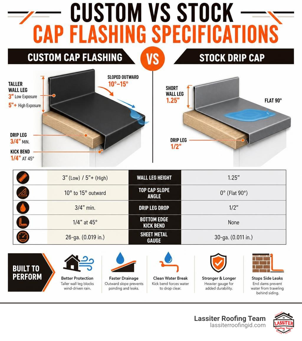
Wall Leg Height: The vertical leg extending up behind siding or housewrap must measure at least 3 inches tall in low-exposure zones and 5 inches or taller in high-wind, high-exposure environments. Over deck ledgers, a 5-to-8-inch leg prevents wind-driven rain from breaching the top edge.
Cap Slope Angle: Never bend cap legs at a flat 90-degree angle. Sloping the top leg outward at 10 to 15 degrees speeds water runoff and prevents standing water from pooling along seams.
Drip Leg Hem and Kick Bend: The front face dropping over the trim should feature a minimum 3/4-inch drip leg ending in a folded hem and a 1/4-inch outward kick bend (bent to roughly 90–95 degrees relative to the cap). This kick forces falling droplets to break free from the metal rather than crawling back beneath the trim.
End Dams: Terminating flashing with flat cut ends lets water spill sideways behind vertical siding. Folding upturned end dams or turn-down closures stops lateral moisture entry.
To review additional structural geometry considerations, refer to this detailed article on Better Window, Door, and Trim Cap Flashing - Fine Homebuilding.
Step-by-Step Cap Flashing Installation Guide
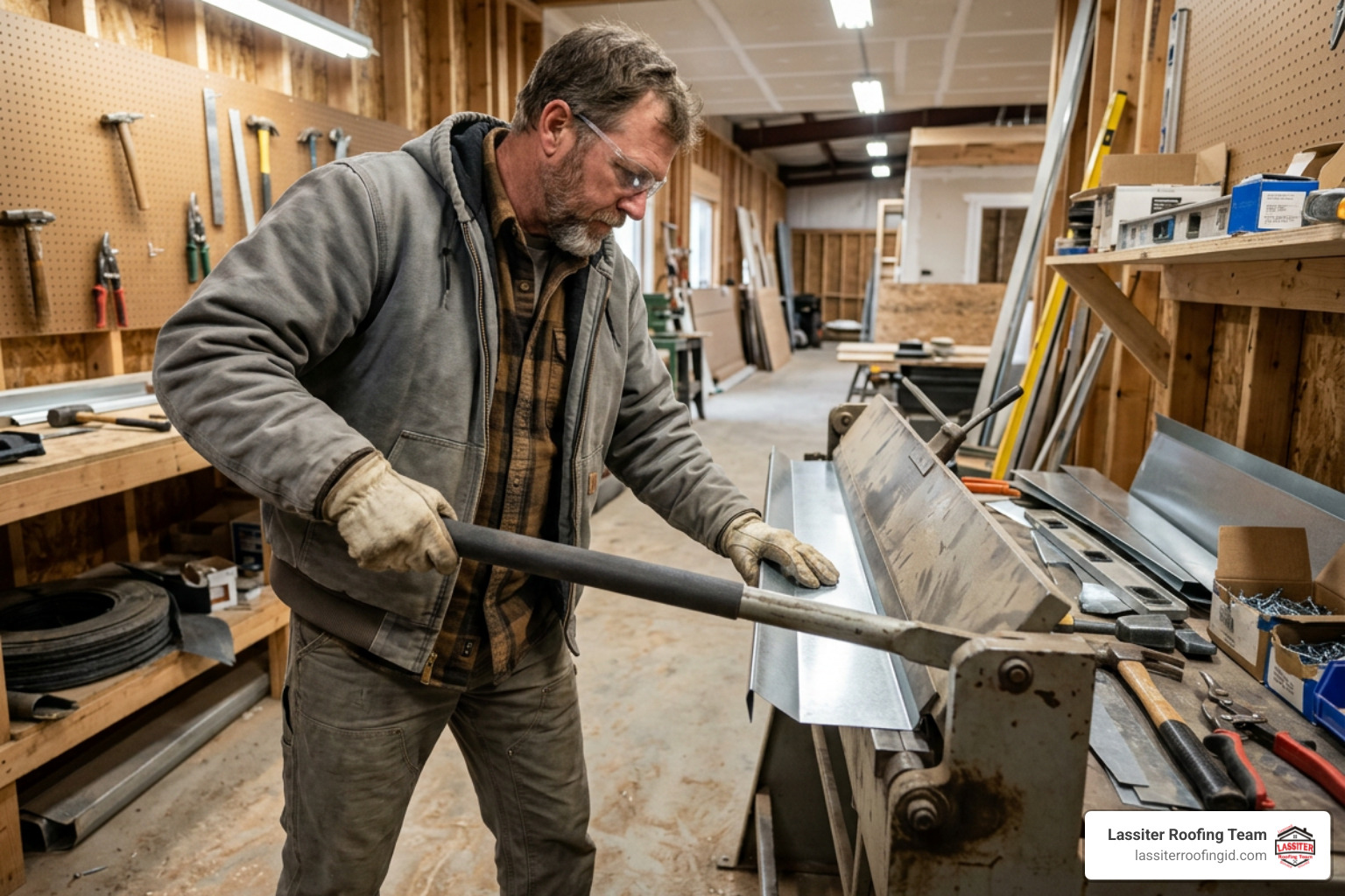
Executing a professional cap flashing installation requires the right tools, proper sequencing, and precision metal work. Standard equipment includes a portable 10-foot or 12-foot sheet metal brake, aviation snips, a hand seamer, a combination square, corrosion-resistant fasteners, and compatible sealant.
Step 1: Pre-Installation Surface Preparation and Measurement
Begin by inspecting the substrate. The underlying wall sheathing, wood trim, or masonry must be clean, dry, and structurally sound.
Clean the Surface: Remove old caulk, loose mortar, or protruding nails.
Test Substrate Moisture: For wood framing, verify that core moisture levels are below 20% using a calibrated meter.
Take Individual Measurements: Avoid "gang-cutting" flashings to equal lengths across older buildings. Measure each window, door, or wall segment individually, adding 1 extra inch to total length measurements to accommodate 1/2-inch end dam folds on both sides.
Integrate Water-Resistive Barriers (WRB): Slice an angled flap in the housewrap or weather barrier directly above the opening so the flashing wall leg sits directly against the sheathing beneath the WRB layer.
Step 2: Custom Bending and Cap Flashing Installation Techniques
Using a sheet metal brake and 0.019-inch metal stock, bend the cap flashing profile to fit the specific wall transition:
Form the Wall Leg: Bend the back leg up at an acute angle to match the wall alignment (minimum 3 to 5 inches tall).
Bend the Sloped Cap: Set the top cap width to match the trim or wall depth plus 1/4 inch, creating a downward outward slope of 10 to 15 degrees.
Shape the Drip Leg and Kick: Fold a 3/4-inch downward drip leg, ending with a folded hem and a 1/4-inch outward kick bend.
Mounting: Position the metal cap snugly against the trim head or parapet wall.
Fastening: Secure the upper wall leg to wall sheathing using stainless steel ring-shank nails or screws equipped with neoprene washers spaced every 12 to 18 inches. Crucial rule: Never drive nails directly through the horizontal sloped cap surface!
Step 3: Integrating Joints and Terminations for Cap Flashing Installation
Where flashing runs exceed 10 or 12 feet—or terminate at wall corners—proper jointing preserves system integrity.

Overlap Seams Correctly: Overlap adjacent flashing sections by at least 3 inches in the direction of primary water flow.
Seal Seams: Apply two continuous beads of high-grade polyurethane or silicone sealant between overlapping metal faces before joining them.
Fabricate End Dams: At the ends of window caps or wall edges, notch the drip leg and sloped cap with aviation snips. Bend the edge flaps up 90 degrees using a hand seamer to create an upturned end dam, stopping water from running sideways into trim side seams.
Lap Weather Barriers Shingle-Fashion: Drop the upper WRB housewrap flap back down over the top of the flashing wall leg. Tape vertical WRB seams with approved flashing tape to establish a continuous drainage barrier.
For comprehensive steps on integrating flat roof membrane perimeter caps, read this breakdown on Flat Roof Cap Flashing: Proper Installation, Common Issues, and Maintenance – New England Metal Roof.
Avoiding Critical Errors and Seal Failures
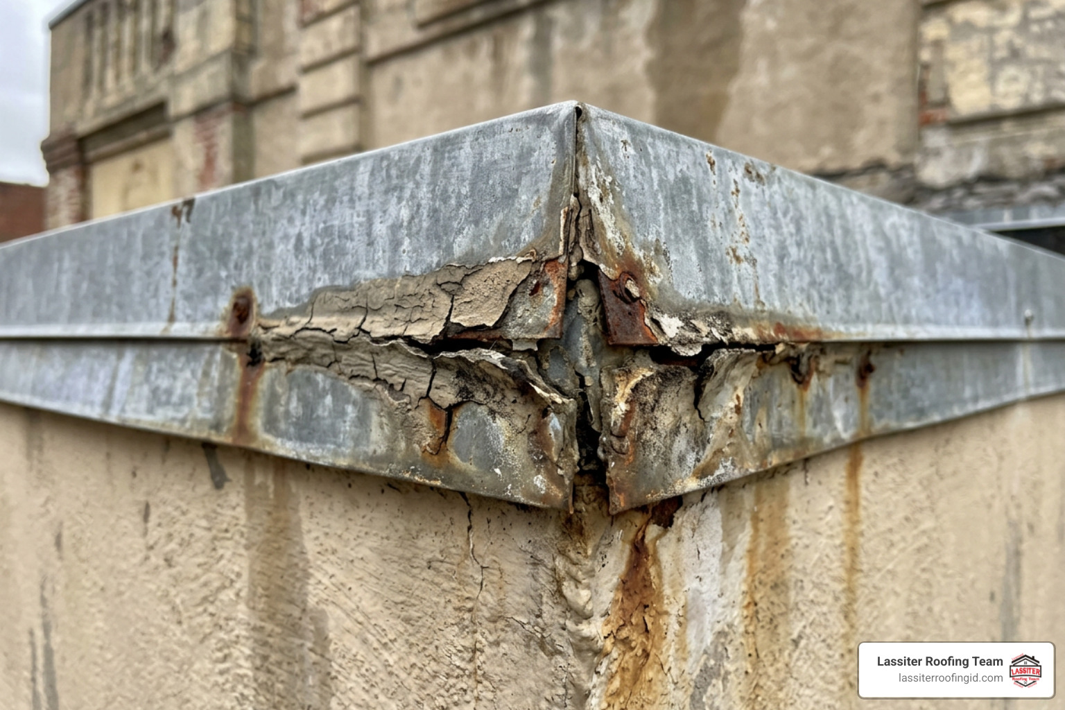
Even minor oversights during cap flashing installation can severely compromise the weatherproofing of an entire building envelope. Up to 30% of residential roof leaks originate from compromised edge components like flashing transitions.
Key Preventative Measures for Installation Longevity
Never Nail to Both Wall and Roof Deck: Fastening a single rigid metal piece to two distinct structural planes prevents natural thermal expansion and contraction. As temperatures cycle, locked metals buckle, pull out fasteners, or tear open sealant joints. Always anchor cap flashing to the wall leg or continuous cleat, letting base components float underneath.
Eliminate Flat Profiles: A flat 90-degree cap flashing allows water to pond along horizontal surfaces. Standing water breaks down sealants, accelerates corrosion, and seeps through micro-fissures during freeze-thaw cycles.
Avoid Dissimilar Metal Contact: Direct contact between incompatible metals (such as copper touching galvanized steel or aluminum) causes galvanic corrosion. Use stainless steel fasteners or inert isolation tapes when joining dissimilar materials.
Maintain Cladding Clearance: Always leave a 1/4-inch to 1/2-inch air gap between the bottom edge of siding panels and the sloped surface of the cap flashing below. Installing siding flush against flashing traps water against cladding, causing cedar rot or fiber cement edge breakdown.
Verify Chemical Compatibility: Ensure rubberized bitumen membrane tapes, liquid sealants, and metal coatings are chemically compatible with the underlying roofing material or roof membrane (e.g., TPO or EPDM).
Maintenance and Inspection Protocol
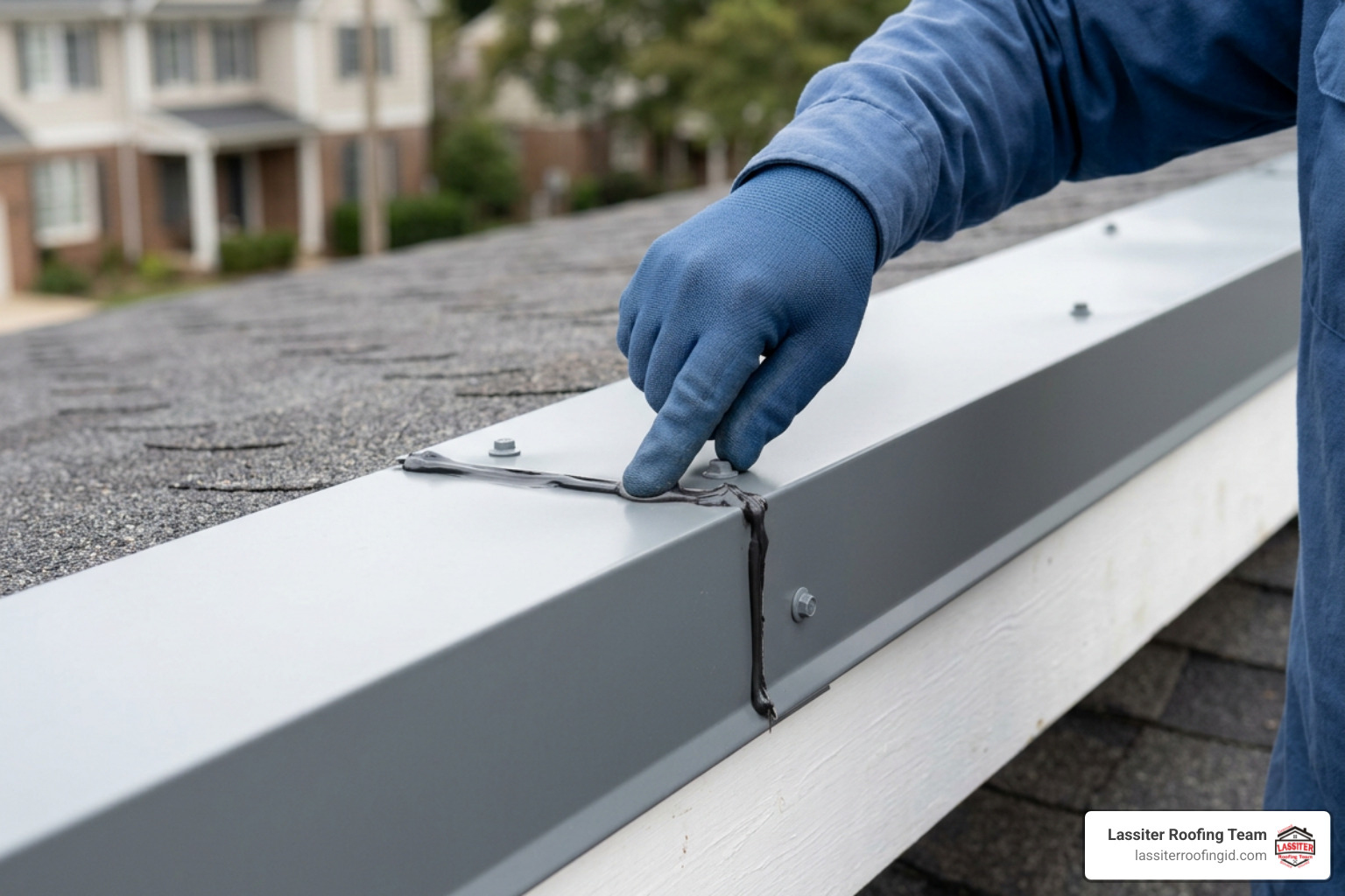
Regular maintenance extends cap flashing performance and catches potential failure points before internal damage develops.
We recommend inspecting perimeter cap flashings at least twice a year—in spring and autumn—as well as immediately following severe windstorms or hail events.
Diagnostic Inspection Procedures
Check Exterior Alignment: Look for loose fasteners, lifted metal edges, wind deformation, or sagging seams along parapet edges and window heads.
Examine Sealant Joints: Inspect lap sealants for cracking, shrinkage, UV chalking, or physical separation from metal surfaces.
Use the 45-Degree Light Method: Shine a flashlight across metal lap seams at a 45-degree angle. Shadow lines reveal minor air pockets, buckled edges, or unbonded seams as small as 0.5 millimeters.
Clear Debris and Maintain Clearances: Sweep away trapped pine needles, leaves, and dirt from drip legs and water pathways to eliminate standing moisture traps.
Conduct Spray Pressure Tests: When troubleshooting hidden leaks, apply a controlled water spray test at 30 psi starting at the bottom of the assembly and working slowly upward for 10 minutes to verify joint performance.
For specialized repair procedures when restoring compromised metal caps, consult this professional guide on 10 Steps to Fix Metal Cap Flashing Like a Pro - RoofIntellect.
Frequently Asked Questions about Cap Flashing
What is the minimum building code requirement for metal cap flashing thickness?
Under the International Residential Code (IRC Section R703.4) and standard building codes, exterior wall cap flashing must be constructed from corrosion-resistant metal with a minimum thickness of 0.019 inches (26-gauge sheet metal). Standard store-bought stock flashings manufactured at 0.011 inches do not meet this minimum structural baseline and are far more prone to wind lift and premature corrosion.
Why should cap flashing be custom-bent rather than bought off-the-shelf?
Pre-formed off-the-shelf stock cap flashings sold at big-box hardware stores usually feature short 1-1/4-inch wall legs, flat 90-degree angles, thin gauge metal, and lack proper drip kick bends. Custom bending metal on a sheet metal brake allows us to size the wall leg to match localized exposure requirements (3 to 5+ inches), introduce a 10-to-15-degree outward drainage slope, form hemmed kick edges, and craft folded end dams tailored precisely to your building's trim dimensions.
How do end dams prevent water intrusion at wall trim terminations?
End dams are upturned metal tabs formed by snip-cutting and bending the side ends of a cap flashing 90 degrees upward prior to mounting. When wind-driven rain hits the sloped face of a cap flashing, water naturally flows laterally toward the left and right ends. Without upturned end dams, this water spills off the sides directly behind the vertical siding and corner trim, soaking interior framing. End dams block lateral flow and force water outward onto the face of exterior cladding.
Conclusion
Mastering cap flashing installation comes down to respecting water dynamics and building codes. By choosing 26-gauge corrosion-resistant metals, custom-bending sloped profiles with hemmed drip kicks, maintaining positive shingle-fashion overlaps, and folding watertight end dams, you protect your property against structural decay and expensive water intrusion.
At Lassiter Roofing, we bring over 30 years of hands-on expertise to every residential, commercial, and agricultural project across Idaho's Western Treasure Valley. Whether you are installing a new roof system, replacing parapet coping, or repairing chronic wall leaks, our team backs every job with individually quoted competitive pricing and a 5-year workmanship warranty.
Contact us today to schedule a thorough roof edge inspection or explore our complete lineup of Expert Roofing Services tailored to keep your building secure in every season.


